FAQ

If you suspect your thermocouple is providing incorrect temperature measurements, there are several steps you can take to diagnose and resolve the issue.

1. Verify the Measurement Setup

Before assuming the thermocouple is faulty, check the following:

  • Ensure proper connection to the instrumentation (loose or corroded connections can affect readings).
     
  • Confirm that the correct thermocouple type (e.g., Type K, J, T, etc.) is selected in the measuring device.
     
  • Inspect the wiring for damage, wear, or reversed polarity.

2. Compare Readings Against a Known Reference

  • Use a secondary temperature sensor (such as a calibrated RTD or another thermocouple) to cross-check readings.
     
  • If possible, place the thermocouple in a controlled temperature source (e.g., an ice bath at 0°C or a dry block calibrator) to verify accuracy.

3. Consider Calibration of the Measurement System

  • Thermocouples themselves are not typically adjusted during calibration. Instead, the electronics that interpret their signal (such as digital displays or data acquisition systems) are calibrated to ensure accurate readings.
     
  • Calibration involves verifying that the system correctly interprets the thermocouple’s voltage output at known temperature points.
     
  • If discrepancies are found, adjustments can often be made to the electronics to correct for any measurement errors.

4. Replace the Thermocouple if Necessary

If the thermocouple consistently provides inaccurate readings and calibration adjustments to the electronics do not resolve the issue, the thermocouple itself may have degraded or drifted beyond acceptable limits. In this case, replacing it is often the best solution.

Would you like assistance in troubleshooting or selecting a replacement thermocouple? Contact us today!

An LVDT (Linear Variable Differential Transformer) core extension rod is a critical component that allows the sensor’s core to move freely while maintaining precise position measurement. It serves as a mechanical link between the LVDT core and the moving target, enabling accurate signal output even in applications where direct coupling to the core is not possible.

a diagram of an lvdt with a core extension rod attached to an object that is being measured

How Does a Core Extension Rod Help?

  1. Extends the Reach of the LVDT Core and Enables Remote or Hard-to-Reach Measurements
    In many applications, the measured target is positioned away from the LVDT sensor. The extension rod bridges this gap, enabling the core to move with the target without repositioning the sensor. It also allows the sensor to be mounted in a protected location, shielding it from harsh environmental conditions while still accurately tracking movement at the measurement point.
     
  2. Supports Customization for Various Applications
    Extension rods can be customized in length, diameter, and material to fit specific application needs. Whether for industrial automation, aerospace, or heavy machinery, the right extension rod can help to ensure optimal sensor performance.

Choosing the Right Core Extension Rod

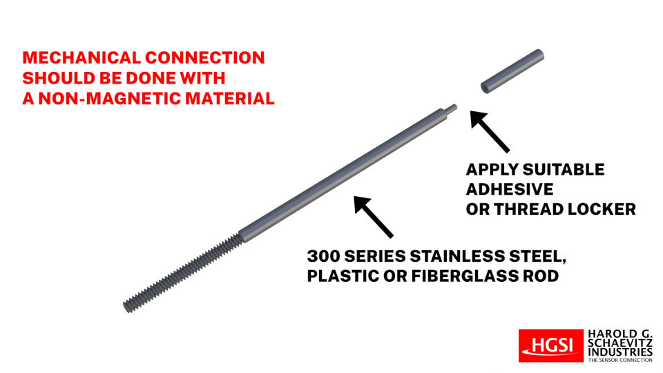
Material Matters – The mechanical connection to the core should be made using a non-magnetic material, preferably 300-series stainless steel, fiberglass, or a plastic rod, secured with a suitable adhesive or thread locker. Highly conductive materials such as aluminum or brass should be avoided, as they may generate eddy currents within the LVDT, leading to unacceptable measurement errors.

Proper Length and Diameter – The rod must be sized appropriately to maintain smooth operation and stability.

Would you like recommendations on LVDT core extension rods for your application? Contact us today!


Both AC and DC LVDTs (Linear Variable Differential Transformers) are used for precise linear position sensing, but they differ in operation, signal processing, and application requirements. Here’s a breakdown of the key differences:

1. Excitation & Signal Processing

  • AC LVDT: Requires an external AC excitation source (typically 1-10 kHz) and signal conditioning to convert the output into a usable DC voltage or current.
     
  • DC LVDT: Contains built-in electronics that provide a DC excitation and output a conditioned analog signal (typically ±10VDC, 0-10VDC or 4-20mA).

2. External Signal Conditioning

  • AC LVDT: Needs an external signal conditioner or amplifier to process the raw AC signal.
     
  • DC LVDT: Has integrated signal processing, eliminating the need for an external conditioner.

3. Electrical Noise & EMI Susceptibility

  • AC LVDT: Less susceptible to electrical noise and ground loops, making it ideal for harsh environments.
     
  • DC LVDT: More susceptible to noise due to built-in electronics, requiring proper shielding and grounding. 

4. Operating Temperature & Environmental Conditions

  • AC LVDT: Handles higher temperatures and more extreme conditions because there are no built-in electronics that could be damaged.
     
  • DC LVDT: Limited by the operating temperature range of its internal electronics.

5. Application Suitability

  • AC LVDT: Best for high-temperature, rugged, or hazardous environments where signal conditioning can be placed remotely.
     
  • DC LVDT: Ideal for simpler applications where ease of installation and a direct signal output are preferred.

Which One Should You Use?

Choose an AC LVDT when environmental conditions are extreme, long cable runs are needed, or high precision with external signal conditioning is required.


Choose a DC LVDT when you need a self-contained solution that’s easy to install with a direct voltage or current output.

Special Limits of Error (SLE) and Class 1 accuracy are similar in that they both refer to higher accuracy thermocouples, but they are not exactly the same because they are defined by different standards with slightly different tolerances.

FeatureClass 1 (IEC 60584-2)Special Limits of Error (ASTM E230)
StandardIEC 60584-2ASTM E230
Primary UsageInternational (Europe, etc.)USA & North America
Accuracy LevelHighHigh
Tolerance DifferencesSlight variations exist by thermocouple typeSlightly different tolerances by type


For many thermocouple types (e.g., Type K), Class 1 and SLE tolerances are very close, but they may not always be identical. If exact compliance with a specific standard is needed, it’s best to compare the tolerances in the respective standards for the given thermocouple type.


StandardClass 1 (IEC 60584-2)Special Limits of Error (ASTM E230)
Class 1 (IEC 60584-2)-40°C to 1000°C±1.5°C or ±0.004×T (whichever is greater)
Primary Usage0°C to 1250°C±1.1°C or ±0.002×T (whichever is greater)

Key Differences

  1. Special Limits of Error (SLE) has a tighter tolerance than Class 1 at most temperatures.

  2. SLE uses a factor of 0.002×T, while Class 1 uses 0.004×T, meaning SLE allows half the percentage error in some cases.

  3. Class 1 covers a lower temperature range (-40°C and up), whereas SLE starts at 0°C.

Summary

  • SLE is more precise than Class 1 at many temperatures.

  • Class 1 allows a slightly larger error margin compared to SLE in most cases.

  • If your application requires the highest accuracy, SLE (ASTM E230) is the better option.

  • If your application requires compliance with IEC standards, Class 1 is the correct classification.

When selecting a thermocouple, accuracy is a critical factor. Two common terms used to define thermocouple accuracy are Accuracy Class and Special Limits of Error (SLE). Here’s how they differ:

1. Accuracy Class

  • Defined by international standards such as IEC 60584-2, each class has specified allowable deviations in temperature measurement based on the thermocouple type..
  • Thermocouples are categorized into different classes based on their accuracy levels:
    • Class 1 – Highest accuracy (tightest tolerances).
    • Class 2 – Standard accuracy (most commonly used).
    • Class 3 – Lower accuracy, typically for extreme low temperatures.
  • Accuracy is typically expressed as a percentage of the temperature range or in degrees (°C or °F).

2. Special Limits of Error (SLE)

  • Defined by ASTM E230 / ANSI MC96.1 (commonly used in the U.S.).
  • SLE thermocouples are manufactured to tighter tolerances than standard thermocouples.
  • SLE thermocouples provide twice the accuracy of standard thermocouples within a defined temperature range.
  • Commonly specified when higher precision is required in industrial and laboratory applications. 


FeatureAccuracy Class (IEC 60584)Special Limits of Error (ASTM E230)
StandardIEC 60584-2ASTM E230
CategoriesClass 1, Class 2, Class 3Standard, Special Limits of Error
AccuracyDefined in °C or % of tempSLE offers higher accuracy than standard
Usage RegionInternational (Europe, etc.)Primarily used in the U.S.

Key Difference:

  • Accuracy Class (IEC-based) refers to defined accuracy levels under international standards.
  • Special Limits of Error (ANSI-based) refers to a tighter accuracy tolerance than standard thermocouples in U.S. standards.

Which One Should You Choose?

Use Class 1 thermocouples or SLE thermocouples when high precision is required.
Class 2 or standard thermocouples are sufficient for general industrial applications where ultra-high accuracy is not necessary.

Why Proper Cable Extension Matters

Extending an LVDT (Linear Variable Differential Transformer) sensor cable requires careful planning to prevent signal degradation caused by noise, impedance mismatch, or voltage drops. Here are best practices to ensure a successful extension:

1. Use Shielded Twisted Pair (STP) Cable

  • Choose a shielded, twisted-pair cable to reduce electromagnetic interference (EMI) and crosstalk.
  • For AC LVDTs, use one twisted pair for excitation lines and another for signal return.
  • For DC LVDTs, use twisted pairs for power, ground, and signal lines to maintain signal quality.

2. If practical, match Cable Specifications

  • Use an extension cable that matches the gauge, impedance, and capacitance of the original cable.
  • Select a low-capacitance cable to preserve signal integrity over long distances.
  • An exact match isn’t always required, but closer specifications reduce the risk of signal issues.

3. Limit Cable Length

  • Keep extensions as short as possible to minimize signal degradation.
  • AC LVDTs: Long cables can impact excitation voltage due to impedance, with a typical max range of 50–100 feet.
  • DC LVDTs: Cables longer than 100 feet may introduce voltage drops in the power supply or signal lines.

4. Consider Signal Conditioning at the Source

  • For long cable runs, place a signal conditioner or amplifier close to the LVDT sensor to convert the signal to a more robust form (e.g., 4–20 mA or ±10 V) that is less susceptible to noise.

5. Grounding and Isolation

  • Ensure proper grounding of the sensor, cable, and signal conditioner to prevent ground loops.
  • If ground loops are a concern, consider using isolated signal conditioners to improve signal stability.

6. Maintain Shield Continuity

  • Connect the cable shield to signal ground at one end only (typically at the signal conditioning or receiving end) to avoid ground loops.
  • Ensure that the shield remains continuous across the entire extension with no breaks or floating segments.

7. Avoid Running Near High-Voltage Lines

  • Keep LVDT cables away from power cables, motors, and high-EMI sources like relays and VFDs (Variable Frequency Drives).

8. Use Cable Trays or Conduits

  • Protect cables in industrial environments using cable trays, conduits, or armored cable to prevent physical damage and EMI interference.

9. Use Proper Connectors

  • Use soldered or crimped connectors designed for signal integrity and environmental protection.
  • For industrial or outdoor environments, consider using IP-rated connectors for additional protection.

10. Verify and Test After Installation

  • After extending the cable, use an oscilloscope or data acquisition system to verify the signal quality.
  • Check for added noise, distortion, or signal offset before putting the system into operation.

Conclusion

By following these best practices, you can extend an LVDT sensor cable while maintaining accuracy and reducing noise interference.